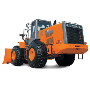
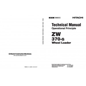
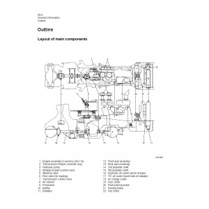
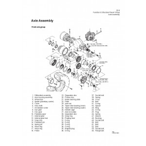
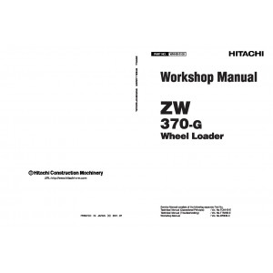
All-Inclusive Factory Service Technical manual for Hitachi Wheel Loaders Models Zaxis ZW370-G.
This manual will assist you in diagnosing, repairing, troubleshooting, and operating for your wheel loader.
Covered Models:
Zaxis ZW370-G
The manual comprises 3 documents, including the Workshop Manual, Troubleshooting Manual, and Operational Principle Manual
1. Workshop Manual (WNHB-E-00)
Format: PDF, 347 pages
Language: English
Table of Contents:
General Information
Symbols
Weight of Main Components
Bolt Tightening Torque
Hose Band Tightening Torque
Liquid Gasket and Screw Lock Agent
Cautions Regarding Welding Repair Service
Cautions Regarding Handling of Bearing
Applying and Storing Articulation Stopper
Disassembly and Reassembly Chassis Group
Deck
Fuel Tank
Hydraulic Tank
Engine Room
Cab
Floor Board
Boom
Center Pin
Service Standard Chassis Group
Linkage
Linkage Pin Standard Clearance Values
Center Pin
Bucket Positioner and Boom Kick-Out
Disassembly and Reassembly Power Group
Power Line
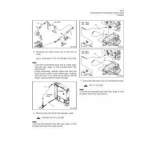
Radiator
Engine
Propeller Shaft
Air Cleaner
Muffler
Fan
Front Axle Assembly
Floating Seal
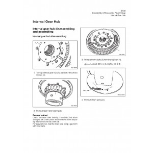
Internal Gear Hub
Spider Assembly
Special Tool
Rear Axle Assembly
Axle Support
Differential Assembly
Service Standard Power Group
Propeller Shaft Service Standard
Axle and Differential Service Standard
Disassembly and Reassembly T/C and T/M Group
Torque Converter and Transmission Assembly
Torque Converter Assembly
Transmission Assembly
Clutch Assembly
Clutch Spider Assembly
Reverse Clutch Spider
Clutch Assembly
High Clutch Assembly
Control Valve Assembly
Service Standard T/C and T/M Group
Transmission Assembly
Torque Converter Gear Pump
Gear Train and Number of Teeth
Clutch Oil Pressure
Disassembly and Reassembly Hydraulic Group
Hydraulic Parts Removal and Installation Warning
Hydraulic Parts Disassembly and Assembly Cautions
Hydraulic Pump Assembly
Hydraulic Cylinder
Pilot Valve
Multiple Control Valve
Orbitrol
Steering Valve
Stop Valve
Fan Motor
Service Standard Hydraulic Group
Hydraulic Cylinder
Pilot Valve
Steering Valve
Disassembly and Reassembly Brake Group
Unloader Valve
Manifold Valve Assembly
Accumulator
Brake Valve
Service Brake
Parking Brake (Rear)
Parking Brake Actuator
Parking Brake (Front) (for Europe only)
Service Standard Brake Group
Brake Valve
Service Brake
Parking Brake
Disassembly and Reassembly Operator Station Group
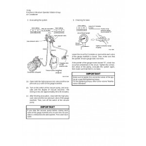
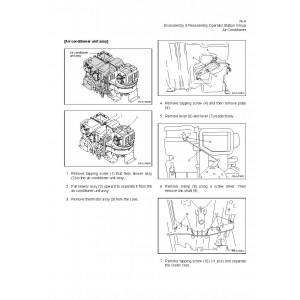
Air Conditioner
Service Standard Operator Station Group
Air Conditioner
2. Troubleshooting Manual (TTNHB-E-00)
Format: PDF, 92 pages
Language: English
Table of Contents:
Troubleshooting 01
Cautions Regarding Troubleshooting
How to Use Quick Troubleshooting Table
Safety Precautions
Torque Converter and Transmission Group
Hydraulic Group
Brake Group
Electrical Group
Operator Station Group
MEASUREMENT FOR PERFORMANCE CHECK 03
Standard Measurement Values for Performance Check
Preparation for Performance Check
Measuring Engine Speed
Measuring Clutch Oil Pressure and Time Lag
Measuring Cylinder Drift
Measuring Boom Cycle Time
Measuring Full Steering Cycle Time
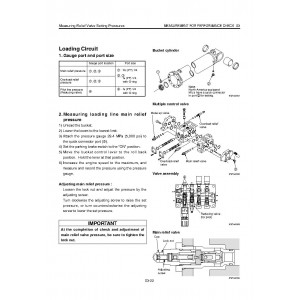
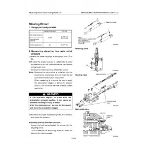
Measuring Relief Valve Setting Pressures
Measuring Fan Revolution
Checking Brake Performance
Measuring Brake Line Oil Pressure
Measuring Accumulator Circuit Charging Time
Measuring Number of Brake Pedal Applications
Measuring Declutch Engagement
Notes
3. Operational Principle Manual (TONHB-E-00)
Format: PDF, 647 pages
Language: English
Table of Contents:
Measurement for Performance Check
Cautions on Safety
Standard Measurement Values for Performance Check
Function and Structure Chassis Group
Front Chassis
Rear Chassis
Center Pin
Check and Adjustment Chassis Group
Linkage Pin
Center Pin
Function and Structure Power Group
Power Line
Engine / Transmission
Radiator
Propeller Shaft
Axle Assembly
Axle Support
Differential Gear
Check and Adjustment Power Group
Engine
Propeller Shaft
Axle
Function and Structure T/C and T/M Group
Torque Converter
Torque Converter Gear Pump
Clutch Pack
Power Flow Path in the Transmission
Hydraulic System Diagram
Hydraulic Circuit Diagram
Oil Flow
T/C and T/M Oil Circulation
Modulator Valve Unit
Modulation Mechanism
Clutch Solenoid Valve
Check and Adjustment T/C and T/M
Clutch Oil Pressure and Time Lag
Function and Structure Hydraulic Group
Flushing Hydraulic Circuit
Cautions on Hydraulic Parts Replacement
Hydraulic Circuit Symbols
Hydraulic System Operation
Layout of Hydraulic Units
Hydraulic Tank
Hydraulic Pump
Hydraulic Cylinder
Loading System
Reducing Valve (for Pilot Pressure)
Pilot Valve (S/N 0101~0290, 9001~9080)
Pilot valve (S/N 0291~0408, 9081~)
Pilot valve (S/N 0409~0410)
Pilot valve (S/N 0411~)
Multiple Control Valve (KML35A/2T003B)
Adapter (Orifice)
Vibration Damper (OPT)
Steering System
Orbitrol
Steering Valve (KVS32-A4.0)
Stop Valve
Reducing Valve (for Orbitrol)
Steering Line Filter
Fan Motor System
Fan Motor Line (S/N 0101~0230)
Fan Motor Line (S/N 0231~)
Fan Motor Line (S/N 9001~9010)
Fan Motor Line (S/N 9011~)
Emergency Steering (for Europe)
Check and Adjustment Hydraulic Group
Loading/Steering Circuit Relief Valve
Hydraulic Cylinder
Stop Valve
Fan Revolution (S/N 0101~)
Fan Revolution (S/N 9001~)
Function and Structure Brake Group
Brake System Outline
Brake Units Layout
Unloader Valve
Valve Unit
Reducing Valve
Brake Accumulator Line
Brake Valve
Stop Lamp Pressure Switch
Service Brake
Parking Brake
Parking Brake (Rear)
Parking Brake (Front) (for Europe only)
Auto Brake
Check and Adjustment Brake Group
Brake Circuit Oil Pressure
Service Brake
Parking Brake
Function and Structure Electrical Group
How to Use Electrical Wiring Diagram
Electrical Cable Color Codes
Electrical Circuit Symbols
Sensor Mount
Fuse
Engine Start Circuit
Power Generating/Charging Circuit
ECM (Engine Controller)
Transmission Control Circuit and Monitor Circuit (S/N 0101~0358, 9001~)
Transmission Control Circuit and Monitor Circuit (S/N 0359~)
Monitoring System
Instrument Panel and Switch
Electrical Detent Circuit
Diode
Diagnostic System
MODM (S/N 97C4-0361~)
Check and Adjustment Electrical Group
Cautions Regarding Electric Circuit Check
Electrical Transmission Control System Troubleshooting Flowchart
Transmission Controller Abnormal Operation Judgment
Electrical Circuit Check
Shift Lever
Function and Structure Operator Station Group
Cabin
Operator Seat
Steering and Transmission Shift Lever
Air Conditioner
Check and Adjustment Operator Station Group
Air Conditioner
Cross-Section Drawing and Diagrams
Axle Assembly
Torque Converter and Transmission
Loading/Steering Hydraulic Line (S/N 0101~0230)
Loading/Steering Hydraulic Line (S/N 0231~)
Loading/Steering Hydraulic Circuit (S/N 9001~9010)
Loading/Steering Hydraulic Circuit (S/N 9011~)
Brake Circuit
Electrical Wiring Diagram (1/2) (S/N 0101~0237)
Electrical Wiring Diagram (2/2) (S/N 0101~0237)
Electrical Wiring Diagram (1/2) (S/N 0238~0242)
Electrical Wiring Diagram (2/2) (S/N 0238~0242)
Electrical Wiring Diagram (1/2) (S/N 0243~0358)
Electrical Wiring Diagram (2/2) (S/N 0243~0358)
Electrical Wiring Diagram (1/3) (S/N 0359~)
Electrical Wiring Diagram (2/3) (S/N 0359~)
Electrical Wiring Diagram (3/3) (S/N 0359~)
Electrical Wiring Diagram (1/2) (S/N 9001~9010)
Electrical Wiring Diagram (2/2) (S/N 9001~9010)
Electrical Wiring Diagram (1/2) (S/N 9011~9064)
Electrical Wiring Diagram (2/2) (S/N 9011~9064)
Electrical Wiring Diagram (1/2) (S/N 9065~9080)
Electrical Wiring Diagram (2/2) (S/N 9065~9080)
Electrical Wiring Diagram (1/2) (S/N 9081~)
Electrical Wiring Diagram (2/2) (S/N 9081~)
Electrical wiring diagram abbreviation chart (S/N 0101~0360, 9001~)
Electrical wiring diagram abbreviation chart (S/N 0361~)
Electrical Wiring Diagram (CAB)
Electrical Connection Diagram (S/N 0101~0237)
Electrical Connection Diagram (S/N 0238~0252)
Electrical Connection Diagram (S/N 0253~0360)
Electrical Connection Diagram (S/N 0361~)
Electrical Connection Diagram (S/N 9001~9064)
Electrical Connection Diagram (S/N 9065~)
Electrical Equipment Layout
Electrical Circuit Diagram (Cabin Air Conditioner)
Electrical Wiring Diagram (Cabin Air Conditioner)
Equipment Operation Table (Cabin Air Conditioner)
| Included in the package | |
| Workshop Manual | 1 |
| Troubleshooting Manual | 1 |
| Operational Principle Manual | 1 |
| Covered | |
| Model Class | ZW370 |
| Generation | G |
| Truck Type | Wheel Loader |
| Truck Models | ZW370-G |
Hitachi Zaxis ZW370-G Wheel Loader set of Service Manuals
- Brands Hitachi
- Product Code:Hitachi::ZW370-G
- Availability:Ready to instant download
-
$23.00
Tags: Zaxis ZW370-G.

