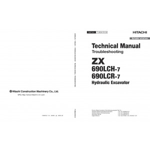
All-Inclusive Factory Service Technical manual for Hitachi Crawler Excavators Models Zaxis 690LCH-7 and Zaxis 690LCR-7.
This manuals will assist you in troubleshooting, repairing engine, and operating for your crawler excavator.
You can use a Windows, Mac, or Android device to view this manuals. You only need to have a PDF reader installed.
Covered Models:
Zaxis 690LCH-7
Zaxis 690LCR-7
The manual comprises 4 documents, including the Troubleshooting Manual, Engine Technical Manual, Operational Principle Manual, and Wiring Diagram
1. Troubleshooting Manual (TTJBQ40-EN-00)
Format: PDF, 651 pages
Language: English
Table of Contents:
OPERATIONAL PERFORMANCE TEST
Introduction
Standard
Engine Test
Machine Performance Test
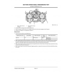
Component Test
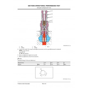
Adjustment
TROUBLESHOOTING
Diagnosing Procedure
Monitor
e-Service
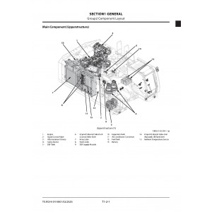
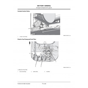
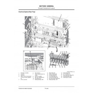
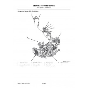
Component Layout
Troubleshooting A
Troubleshooting B
Air Conditioner
2. Engine Technical Manual (6WG1_ENGINE_MANUAL)
Format: PDF, 593 pages
Language: English
Table of Contents:
0 Introduction (All models)
Introduction
14A Service Information Guide (All models)
Contents included in service information
Plastic gauge
Recommended liquid gasket
Thread locking adhesive agent
Term
Abbreviations
Standard bolts
15B Maintenance Information (6WG1)
Maintenance precautions
Primary specifications
Function, Structure, Operation
Introduction to the trouble diagnosis
15C Functional Inspection (6WG1)
Engine compression pressure inspection
Fuel system check
Air intake system check
Exhaust system check
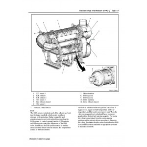
DPD control system check
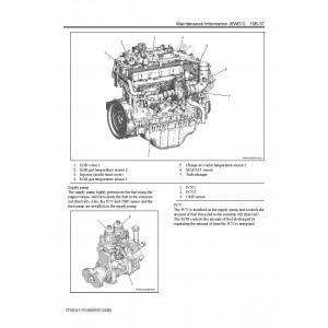
EGR control system check
Starting system check
Glow control system check
OBD system check
Inspection of the diagnostic light warning light illumination circuit system
Inspection of the diagnostic light warning light blinking circuit system
Inspection of the starter circuit system
15D Symptom (6WG1)
Intermittent conditions of engine
Engine start failure
Engine stalling
Engine hunching, rough idling
Excessive white smoke in the exhaust gas
Excessive black smoke in the exhaust gas
Abnormal noise
Large fuel consumption
Large oil consumption
Insufficient engine output
DPD system manual regeneration frequently
DPD system regeneration long time
1A Engine Control (6WG1)
DTC P0016 (Flash Code 16) Crankshaft Position - Camshaft Position Correlation Error
Low Voltage
High Voltage
Range/Performance
Range/Performance Sensor 1
Sensor 1
Sensor 1
Range/Performance Sensor 2
Sensor 2
Sensor 2
Range/Performance
Error
Performance
Shutdown
Circuit
Circuit
1 Circuit Low Voltage
1 Circuit High Voltage
High
High
Performance
Circuit Low
Circuit High
Range/Performance
Position
System Performance
Module
38B Maintenance Information (Urea SCR System)
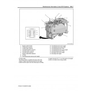
Function, structure, operation of emission control
Introduction to the trouble diagnosis of emission control
38C Functional Inspection (Urea SCR System)
Diagnostic system check-urea selective catalytic reduction system
38D Symptom (Urea SCR System)
Intermittent conditions of urea selective catalytic reduction system
Urea fluid consumption too high
Ammonia smell noticeable
White crystalline powder visible
10M Emission Control (Urea SCR System)
Wiring Diagram
Using the ETM
Engine
Location Diagram
Connector List
Terminal Name
SERVICE MANUAL REVISION REQUEST FORM
3. Operational Principle Manual (TOJBQ40-EN-00)
Format: PDF, 397 pages
Language: English
Table of Contents:
INTRODUCTION
To The Reader
Additional References
Manual Composition
Trademark
Safety Alert Symbol and Headline Notations
Units Used
SYMBOL AND ABBREVIATION
Symbol and Abbreviation
CONTRASTING LIST OF PART NAME
Contrasting List of Part Name between Technical Manual and Parts Catalog
SECTION AND GROUP CONTENTS
GENERAL
Specifications
Component Layout
Component Specifications
SYSTEM
Controller
Control System
Engine System
Hydraulic System
Electrical System
COMPONENT OPERATION
Pump Device
Swing Device
Control Valve
Pilot Valve
Travel Device
Signal Control Valve
Others (Upperstructure)
Others (Undercarriage)
SERVICE MANUAL REVISION REQUEST FORM
4. Wiring Diagram (TTJBQ40-EN-00_Circuit(20200214))
Format: PDF, 25 pages
Language: English
Table of Contents:
ELECTRICAL CIRCUIT DIAGRAM
CONNECTORS
CAB HARNESS
MAIN HARNESS
CAB REAR HARNESS (OPTION)
CONSOLE HARNESS (OPTION)
PUMP HARNESS
NOx HARNESS
MONITOR HARNESS
CONSOLE HARNESS
CONTROL VALVE HARNESS
WIPER HARNESS
WIPER MOTOR HARNESS
PILOT SHUT-OFF SOLENOID VALVE HARNESS
ENGINE STOP SWITCH HARNESS
CAMERA LIGHT HARNESS
ENGINE HARNESS
REAR VIEW CAMERA HARNESS
BOOM LIGHT HARNESS
24V SOCKET HARNESS
WORK LIGHT HARNESS
OIL COOLER HARNESS
BOX HARNESS
HYDRAULIC CIRCUIT DIAGRAM
HYDRAULIC CIRCUIT DIAGRAM (BREAKER/CRUSHER)
| Included in the package | |
| Troubleshooting Manual | 1 |
| Engine Technical Manual | 1 |
| Operational Principle Manual | 1 |
| Wiring Diagram | 1 |
| Covered | |
| Model Class | ZAXIS 690 |
| Generation | 7 |
| Truck Type | Crawler Excavator |
| Truck Models | ZAXIS 690LCH-7, ZAXIS 690LCR-7 |
Hitachi Zaxis 690LCH-7 and Zaxis 690LCR-7 Crawler Excavator set of Service Manuals
- Brands Hitachi
- Product Code:Hitachi::ZX690-7
- Availability:Ready to instant download
-
$23.00
Tags: Zaxis 690LCH-7, Zaxis 690LCR-7

