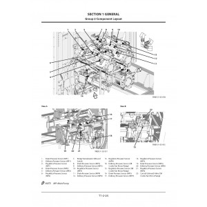
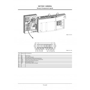
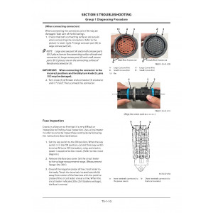
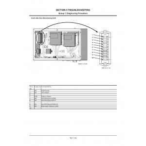
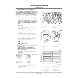
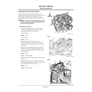
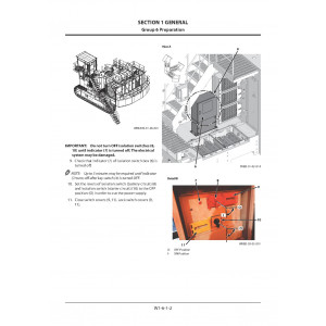
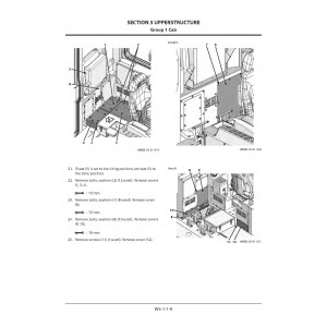
All-Inclusive Factory Service Technical manual for Hitachi Hydraulic Excavators Models EX2600-7B with Tier 4 Final Cummins Engine .
This manuals will assist you in diagnosing, repairing, determining a malfunction using a fault code, troubleshooting, operating, assembling, and checking for your hydraulic excavator.
You can use a Windows, Mac, or Android device to view this manuals. You only need to have a PDF reader installed.
Covered Models:
EX2600-7B (Tier 4 Final Cummins Engine)
The manual comprises 10 documents, including the Workshop Manual, Fault Codes List, Troubleshooting Manual, Operational Principle Manual, Operators Manual, Wiring Diagram, Assembly Manual, and three Check Sheets
1. Workshop Manual (WKEB90EN00)
Format: PDF, 1339 pages
Language: English
Table of Contents:
GENERAL
Precautions for Disassembling and Assembling
Tightening
Painting
Bleeding Air
Releasing Pressure
Preparation
MAINTENANCE STANDARD
Upperstructure
Undercarriage
Loader Front Attachment
Backhoe Front Attachment
UPPERSTRUCTURE
Cab
Cab Bed
Counterweight
Upperstructure
Engine Unit
Pump Device
Control Valve
Other Valves
Swing Device
Aftertreatment Device
Hydraulic Oil Tank
Fuel Tank
Lift Cylinder (Fast-Filling System)
Lift Cylinder (Folding Stairway)
UNDERCARRIAGE
Swing Bearing
Travel Device
Travel Brake Valve
Drive Tumbler
Center Joint
Adjuster Cylinder
Front Idler
Upper and Lower Roller
Track
Accumulator
Welding Repair Procedure
LOADER FRONT ATTACHMENT
Front Attachment
Cylinder
Bushing
Angle Sensor
Other Valves
BACKHOE FRONT ATTACHMENT
Front Attachment
Cylinder
Bushing
Angle Sensor
Other Valves
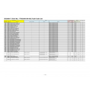
2. Fault Codes List (TTKEA90EN0ECL)
Format: PDF, 35 pages
Language: English
3. Troubleshooting Manual (TTKEB90EN00)
Format: PDF, 349 pages
Language: English
Table of Contents:
OPERATIONAL PERFORMANCE TEST
Introduction
Standard
Engine Test
Machine Performance Test
Component Test
TROUBLESHOOTING
Diagnosing Procedure
Monitor
Cross Reference Table
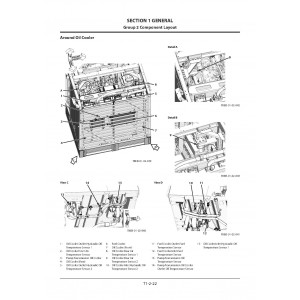
Component Layout
Troubleshooting for Each Code
Air Conditioner
e-Service
Aftertreatment Device
4. Operational Principle Manual (TOKEB90EN00)
Format: PDF, 395 pages
Language: English
Table of Contents:
GENERAL
Specifications
Component Layout
Component Specifications
SYSTEM
Controller
Control System
ELU System
Hydraulic System
Electrical System
Air Conditioning System
COMPONENT OPERATION
Pump Device
Swing Device
Control Valve
Control Equipment
Travel Device
Others (Upperstructure)
Others (Undercarriage)
Others (Front Attachment)
5. Operators Manual (ENMKEB13)
Format: PDF, 376 pages
Language: English
Table of Contents:
INTRODUCTION
INDEX
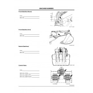
MACHINE NUMBERS
SAFETY
VISIBILITY MAP
SAFETY SIGNS
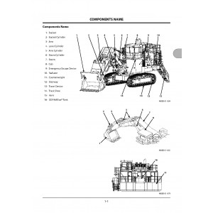
COMPONENTS NAME
GETTING ON AND OFF THE MACHINE
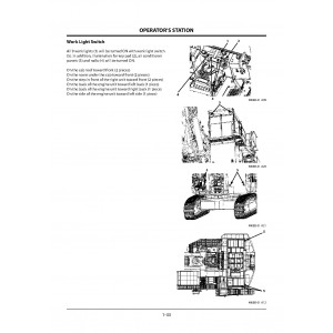
OPERATOR’S STATION
BREAK-IN
OPERATING ENGINE
DRIVING MACHINE
OPERATING MACHINE
TRANSPORTING
MAINTENANCE
HYDRAULIC CIRCUIT
MAINTENANCE UNDER SPECIAL ENVIRONMENTAL CONDITIONS
STORAGE
TROUBLESHOOTING
SPECIFICATIONS
INDEX
6. Wiring Diagram (TTKEB90EN00CIR)
Format: PDF, 16 pages
Language: English
Table of Contents:
ELECTRICAL CIRCUIT DIAGRAM (1/12)
ELECTRICAL CIRCUIT DIAGRAM (2/12)
ELECTRICAL CIRCUIT DIAGRAM (3/12)
ELECTRICAL CIRCUIT DIAGRAM (4/12)
ELECTRICAL CIRCUIT DIAGRAM (5/12)
ELECTRICAL CIRCUIT DIAGRAM (6/12)
ELECTRICAL CIRCUIT DIAGRAM (7/12)
ELECTRICAL CIRCUIT DIAGRAM (8/12)
ELECTRICAL CIRCUIT DIAGRAM (9/12)
ELECTRICAL CIRCUIT DIAGRAM (10/12)
EX2600-7B ELECTRICAL CIRCUIT DIAGRAM (11/12)
ELECTRICAL CIRCUIT DIAGRAM (12/12)
EX2600-7B ELECTRICAL CIRCUIT DIAGRAM (AERIALANGLE)
EX2600-7B ELECTRICAL CIRCUIT DIAGRAM (CAMERA)
CONNECTORS
EX2600-7 HYDRAULIC CIRCUIT DIAGRAM (BACKHOE)
7. Assembly Manual (PMKEB91ENAM01)
Format: PDF, 453 pages
Language: English
Table of Contents:
Assembly Process Chart
LOADER FRONT
BACKHOE FRONT
1 Safety precautions
2 How to use a power wrench
3 Work precautions
1. Workers plan
1-1 Workers plan
1-2 Transportation
2. Parts check
2-1 Check
3. Preparations
3-1 Preperations (Loader front)
3-2 Preparations (Backhoe front)
4. Machines, apparatus, tools and materials necessary for assembly
4-1 Standard tools and lifting points
4-2 Special tools (ST)
5. Assembly of Undercarriage
5-1 Preparation
5-2 Assembly of track links and side frames
5-3 Connection of track frame and side frames
5-4 Connection of travel motor hoses, adjuster hoses and travel motor guards
5-5 Assembly of travel motor guards (Option)
5-6 Assembly of mission guards (Option)
5-7 Assembly of belly plates (Option)
5-8 Disassembly procedures for shipment
6. Connection of undercarriage and superstructure
6-1 Preparations before connection
6-2 Preparation of undercarriage
6-3 Preparation of base machine
6-4 Connection of undercarriage and base machine
6-5 Connection of piping to center joint
6-6 Assembly of fuel tank
6-7 Assembly of cab and escape-device
6-8 Assembly of fenders, steps, handrails, ladder, beam, box and covers
6-9 Assembly of engine unit
6-10 Mounting the counterweight & Installation the DEF tank and DEF pump
6-11 Assembly of intake unit / exhaust unit, water tank and duct
6-12 Assembly head lamps, mirror, switch box, working lamp and motion alarm
6-13 Connection
6-14 Checking the stop valves and stopcocks
6-15 Final check of superstructure
6-16 Releasing air from main pumps
6-17 Trial operation of superstructure
6-18 Disassembly procedures for shipment
6-19 Assembly of monitors
7. Mounting procedures for loader front
7-1 Preparation
7-2 Mounting of loader front
7-3 Mounting of bucket
7-4 Adjustment of track link tension
7-5 Final trial operation check
7-6 Disassembly procedures for shipment
7. Mounting procedures for backhoe front
7-1 Preparation
7-2 Mounting of boom
7-3 Installation of arm
7-4 Mounting the bucket
7-5 Adjustment of track link tension
7-6 Final trial operation check
7-7 Assembly of option parts
7-8 Disassembly procedures for shipment
8. Checks after completing the assembly
9. Checking machine performance
10. Assembly check sheet
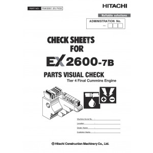
8. Check Sheets: Parts Visual Check (PMKEB91ENPV00)
Format: PDF, 55 pages
Language: English
Table of Contents:
EX2600-7B-ND-00129-PMKEB91-EN-PV00-01
CHECK SHEETS FOR EX2600-7B
EX2600-7B-ND-00129-PMKEB91-EN-PV00-02
INTRODUCTION
INSPECTION PROCEDURE
PRECAUTIONS FOR INSPECTION
PRECAUTIONS IN USING THE PARTS VISUAL CHECK SHEET
EX2600-7B-ND-00129-PMKEB91-EN-PV00-03
PIPING SYSTEM
EX2600-7B-ND-00129-PMKEB91-EN-PV00-04
ELECTRIC PARTS
IMPORTANT CHECKS
9. Check Sheets: Monthly Maintenance (PMKEB91ENMM00)
Format: PDF, 18 pages
Language: English
Table of Contents:
EX2600-7 MONTHLYMAINTENANCE
REPLACEMENT ITEMS-1
REPLACEMENT ITEMS-2
CLEANING ITEMS
VISUAL CHECK ITEMS
GREASING and DRAINING ITEMS
CHECK SHEETS FOR Initial 50 HOURS to 2000 HOURS
10. Check Sheets: Daily and Weekly Maintenance (PMKEB91ENDW00)
Format: PDF, 5 pages
Language: English
Table of Contents:
CHECK POINT-1 : HYDRAULIC , ENGINE COMPONENTS
CHECK POINT-2 : FRONT ATTACHMENT
CHECK POINT-3 : ELECTRIC COMPONENTS
DAILY AND WEEKLY CHECK SHEETS FOR EX2600-7B
| Included in the package | |
| Workshop Manual | 1 |
| Fault Codes List | 1 |
| Troubleshooting Manual | 1 |
| Operational Principle Manual | 1 |
| Operators Manual | 1 |
| Wiring Diagram | 1 |
| Assembly Manual | 1 |
| Check Sheets | 3 |
| Covered | |
| Model Class | EX2600 |
| Generation | 7B |
| Truck Type | Hydraulic Excavator |
| Truck Models | EX2600-7B |
Hitachi EX2600-7B Hydraulic Excavator set of Service Manuals
- Brands Hitachi
- Product Code:Hitachi::EX2600-7B
- Availability:Ready to instant download
-
$23.00

