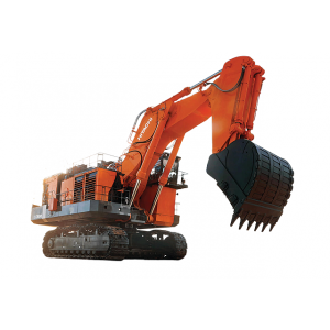
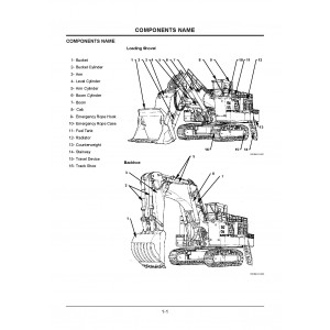
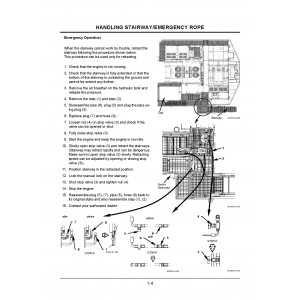
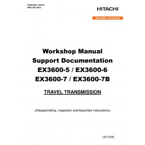
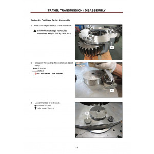
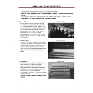
All-Inclusive Factory Service Technical manual for Hitachi Hydraulic Excavators Models EX3600-6.
This manuals will assist you in diagnosing, repairing, troubleshooting, operating, assembling, and checking for your hydraulic excavator.
You can use a Windows, Mac, or Android device to view this manuals. You only need to have a PDF reader installed.
Covered Models:
EX3600-6
The manual comprises 17 documents, including three Workshop Manuals, the Troubleshooting Manual, Operational Principle Manual, four Operators Manuals, Wiring Diagram, Assembly Manual, and 6 Check Sheets
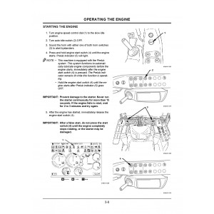
1. Workshop Manual: Travel Transmission (WSDTDE188)
Format: PDF, 154 pages
Language: English
2. Workshop Manual: Travel Transmission (WSDTDE1882)
Format: PDF, 150 pages
Language: English
3. Workshop Manual (W18ME00)
Format: PDF, 526 pages
Language: English
Table of Contents:
GENERAL INFORMATION
Precautions for Disassembling and Assembling
Tightening Torque
Painting
Bleeding Air from Hydraulic OilTank
UPPERSTRUCTURE
Cab
Counterweight
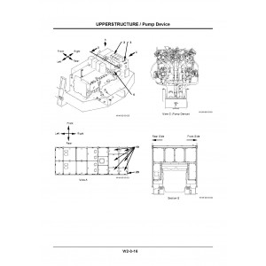
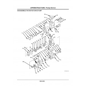
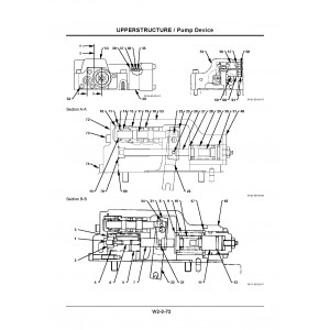
Pump Device
Control Valve
Swing Device
DQR Valve
Shuttle Valve
8-Spool Solenoid Valve
Oil Cooler Fan Motor
Radiator Fan Motor
Compressor Drive Motor
Air Conditioner
Lift Cylinder (Fast-Filling/Draining Device)
Lift Cylinder (Sliding Fold-In Ladder)
UNDERCARRIAGE
Swing Bearing
Travel Device
Travel Brake Valve
Drive Tumbler
Center Joint
Adjuster Cylinder
Front Idler
Upper and Lower Roller
Track
Accumulator
Welding Repair Procedure
FRONT ATTACHMENT
Front Attachment
Cylinder
Bushing and Point
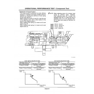
4. Troubleshooting Manual (TT18ME00)
Format: PDF, 250 pages
Language: English
Table of Contents:
OPERATIONAL PERFORMANCE TEST
Introduction
Standard
Engine Test
Excavator Test
Component Test
TROUBLESHOOTING
General
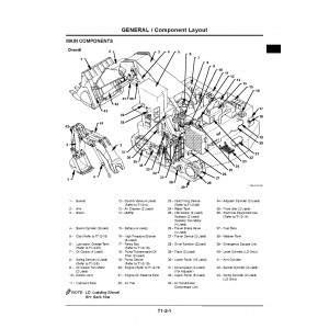
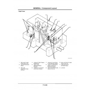
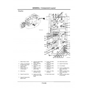
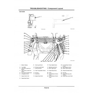
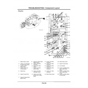
Component Layout
Troubleshooting A
Troubleshooting B
Troubleshooting C
Electrical System Inspection
5. Operational Principle Manual (TO18ME00)
Format: PDF, 270 pages
Language: English
Table of Contents:
GENERAL
Specifications
Component Layout
Component Specifications
SYSTEM
Controller
Control System
ELU System
Hydraulic System
Electrical System
COMPONENT OPERATION
Pump Device
Swing Device
Control Valve
Control Equipment
D.Q.R Valve
Travel Device
Others (Upperstructure)
Others (Undercarriage)
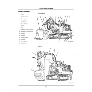
6. Operators Manual (EM18M12)
Format: PDF, 308 pages
Language: English
7. Operators Manual: Quick Visual Inspection (Loader Front) (KO44502)
Format: PDF, 248 pages
Language: English
8. Operators Manual: Quick Visual Inspection (Backhoe Front) (KO41502)
Format: PDF, 248 pages
Language: English
9. Operators Manual (EM18M11)
Format: PDF, 307 pages
Language: English
10. Wiring Diagram (TT18ME00CIR)
Format: PDF, 11 pages
Language: English
Table of Contents:
EX1900-6,EX2600-6,EX3600-6 ELECTRICAL CIRCUIT DIAGRAM (CAB)
EX1900-6(Up to serial No.1068), EX2500-6(Up to serial No.1087), EX3600-6(Up to serial No.1090) ELECTRICAL CIRCUIT DIAGRAM (ELECTRICAL EQUIPMENT BOX 1/2)
EX1900-6(Serial No.1069 and up), EX2500-6(Serial No.1088 and up), EX3600-6(Serial No.1091 and up) ELECTRICAL CIRCUIT DIAGRAM (ELECTRICAL EQUIPMENT BOX 1/2)
EX1900-6,EX2600-6,EX3600-6 ELECTRICAL CIRCUIT DIAGRAM (ELECTRICAL EQUIPMENT BOX 2/2)
EX3600-6 ELECTRICAL CIRCUIT DIAGRAM (MACHINE LEFT)
EX3600-6 ELECTRICAL CIRCUIT DIAGRAM (MACHINE CENTER)
EX3600-6 ELECTRICAL CIRCUIT DIAGRAM (MACHINE RIGHT)
EX1900-6,EX2600-6,EX3600-6 ELECTRIC CONNECTORS
EX3600-6 HYDRAULIC CIRCUIT DIAGRAM (BACKHOE)(Selial No.1001)
EX3600-6 HYDRAULIC CIRCUIT DIAGRAM (BACKHOE)(Serial No.1002 AND AFTER)
EX3600-6 HYDRAULIC CIRCUIT DIAGRAM (LOADING SHOVEL)
11. Assembly Manual (KO32601)
Format: PDF, 401 pages
Language: English
Table of Contents:
1. Precautions
1-1 Safety precautions for servicemen
1-2 How to use a power wrench
1-3 Work precautions
2. Workers plan
2'. Workers plan
2-1 Transportation of Loader Front
2-1' Transportation of Backhoe Front
3. Parts check
4. Preparations (loader front)
4'. Preparations (backhoe front)
5. Machines, apparatus, tools, and materials necessary for assembly
6. Assembly of undercarriage
6-1 Preparation
6-2 Connection of track frame and side frames
6-3 Connection of travel motor piping and adjuster piping
6-4 Assembly of motor covers and step
6-5 Disassembly procedures for shipment (Procedure, Track)
6-6 Assembly of travel motor guard and mission guard(option)
7. Connection of undercarriage and superstructure
7-1 Preparations before connection
7-2 Preparation of undercarriage
7-3 Preparation of main frame
7-4 Connection of undercarriage and main frame assembly
7-5 Connection of piping to center joint
7-6 Assembly of bed (left)
7-7 Assembly of bed (right)
7-8 Installation of bed (right)
7-9 Installation of bed (left)
7-10 Assembly of engine unit
7-11 Mounting of counterweight & reserve tank
7-12 Connecting of various sections
7-13 Checking of stop valves
7-14 Final check of superstructure
7-15 Releasing air from main pumps
7-16 Trial operation of superstructure
7-17 Disassembly procedures for shipment
7-18 Assembly of parts (option)
8. Mounting procedure for loader front-end attachment
8-1 Preparation
8-2 Mounting of boom
8-3 Installation of bucket cylinders
8-4 Mounting of arm
8-5 Mounting of bucket
8-6 Releasing air from the cylinders
8-7 Adjustment of track link tension
8-8 Final trial operation check
8-9 Disassembly procedures for shipment
8'. Mounting procedure for backhoe front-end attachment
8'-1 Preparation
8'-2 Mounting of boom
8'-3 Installation of arm
8'-4 Mounting of bucket
8'-5 Releasing air from the cylinders
8'-6 Adjustment of track link tension
8'-7 Final trial operation check
8'-8 Disassembly procedures for shipment
9. Checks after completing the assembly
10. Checking machine performance
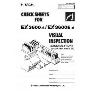
12. Check Sheets: Visual Inspection (Backhoe Front) (KO361B03)
Format: PDF, 37 pages
Language: English
13. Check Sheets: Daily and Weekly Maintenance (KO33300)
Format: PDF, 4 pages
Language: English
14. Check Sheets: Monthly Maintenance (KO33400)
Format: PDF, 73 pages
Language: English
Table of Contents:
CHECK SHEETS FOR EX3600-6
1 50 HOURS to 1250 HOURS
2 1500 HOURS to 2500 HOURS
3 2750 HOURS to 3750 HOURS
4 4000 HOURS to 5000 HOURS
5 5250 HOURS to 6250 HOURS
6 6500 HOURS to 7500 HOURS
7 7750 HOURS to 8750 HOURS
8 9000 HOURS to 10000 HOURS
9 10250 HOURS to 11250 HOURS
10 11500 HOURS to 12500 HOURS
11 12750 HOURS to 13750 HOURS
12 14000 HOURS to 15000 HOURS
13 15250 HOURS to 16250 HOURS
14 16500 HOURS to 17500 HOURS
15 17750 HOURS to 18750 HOURS
16 19000 HOURS to 20000 HOURS
EX3600-6 CHECK POINTS : 1
EX3600-6 CHECK POINTS : 2
FOR EX3600-6 PERIODIC REPLACEMENT OF RUBBER HOSES
HOW TO USE THE EX3600-6 SHEETS
15. Check Sheets: UT Inspection (Backhoe Front) (KO38401)
Format: PDF, 64 pages
Language: English
16. Check Sheets: UT Inspection (Loader Front) (KO52601)
Format: PDF, 64 pages
Language: English
17. Check Sheets: Visual Inspection (Loader Front) (KO361L03)
Format: PDF, 39 pages
Language: English
| Included in the package | |
| Workshop Manual | 3 |
| Troubleshooting Manual | 1 |
| Operational Principle Manual | 1 |
| Operators Manual | 4 |
| Wiring Diagram | 1 |
| Assembly Manual | 1 |
| Check Sheets | 6 |
| Covered | |
| Model Class | EX3600 |
| Generation | 6 |
| Truck Type | Hydraulic Excavator |
| Truck Models | EX3600-6 |
Hitachi EX3600-6 Hydraulic Excavator set of Service Manuals
- Brands Hitachi
- Product Code:Hitachi::EX3600-6
- Availability:Ready to instant download
-
$49.90
Tags: EX3600-6

