All-Inclusive Factory Service Technical manual for Hitachi Wheel Loaders Models Zaxis ZW550-6.
This manual will assist you in diagnosing, repairing, troubleshooting, and operating for your wheel loader.
Covered Models:
Zaxis ZW550-6
The manual comprises 9 documents, including two Workshop Manuals, two Troubleshooting Manuals, two Operational Principle Manuals, and three Wiring Diagrams
1. Workshop Manual (WNHK70-EN-00)
Format: PDF, 828 pages
Language: English
Table of Contents:
GENERAL
Precautions for Disassembling and Assembling
Tightening
Painting
Bleeding Air
Pressure Release Procedure
Preparation
MAINTENANCE STANDARD
Body
Front Attachment
BODY
Cab
Counterweight
Center Hinge
Engine
Radiator Assembly
Hydraulic Oil Tank
Fuel Tank
Pump Device
Control Valve
Pilot Valve
Brake Charge Valve
Combination Valve
DEF Tank
Flow Regulator Valve
Cooling Fan System
Aftertreatment Device
Ride Control Valve and Accumulator
Battery Disconnect Switch
TRAVEL SYSTEM
Tire
Drive Unit
Axle
Propeller Shaft
Brake Valve
Steering Valve
Steering Cylinder
Emergency Steering Device
Reducing Valve
Stop Valve
Main Pressure Block
Priority Hammer Valve and Shuttle Valve
Check Valve
Joystick Steering
Axle Oil Cooler
FRONT ATTACHMENT
Front Attachment
Cylinder
2. Workshop Manual (WNHK40-EN-00(20180806))
Format: PDF, 781 pages
Language: English
Table of Contents:
GENERAL
Precautions for Disassembling and Assembling
Tightening
Painting
Bleeding Air
Pressure Release Procedure
Preparation
MAINTENANCE STANDARD
Body
Front Attachment
BODY
Cab
Counterweight
Center Hinge
Engine
Radiator Assembly
Hydraulic Oil Tank
Fuel Tank
Pump Device
Control Valve
Pilot Valve
Brake Charge Valve
Combination Valve
DEF Tank
Flow Regulator Valve
Cooling Fan System
Aftertreatment Device
Ride Control Valve and Accumulator
Battery Disconnect Switch
TRAVEL SYSTEM
Tire
Drive Unit
Axle
Propeller Shaft
Brake Valve
Steering Pilot Valve
Steering Valve
Steering Cylinder
Emergency Steering Device
Reducing Valve
Stop Valve
Main Pressure Block
Priority Hammer Valve and Shuttle Valve
Check Valve
FRONT ATTACHMENT
Front Attachment
Cylinder
3. Troubleshooting Manual (TTNHK70-EN-00)
Format: PDF, 504 pages
Language: English
Table of Contents:
OPERATIONALPERFORMANCE TEST
Introduction
Standard
Engine Test
Machine Performance Test
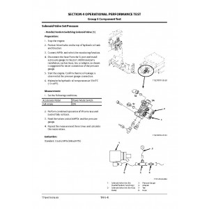
Component Test
Adjustment
TROUBLESHOOTING
Diagnosing Procedure
Monitor
e-Service
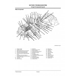
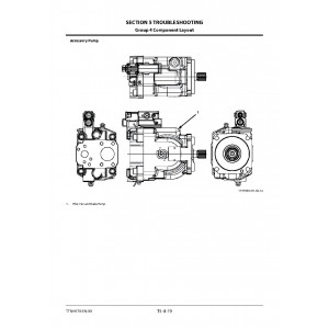
Component Layout
Troubleshooting A
Troubleshooting B
Air Conditioner
SERVICE MANUAL REVISION REQUEST FORM
The Attached Diagram List
4. Troubleshooting Manual (TTNHK40-EN-00(20170510))
Format: PDF, 542 pages
Language: English
Table of Contents:
OPERATIONAL PERFORMANCE TEST
Introduction
Standard
Engine Test
Machine Performance Test
Component Test
Adjustment
TROUBLESHOOTING
Diagnosing Procedure
Monitor
e-Service
Component Layout
Troubleshooting A
Troubleshooting B
Air Conditioner
Joystick Steering System
5. Operational Principle Manual (TONHK70-EN-00)
Format: PDF, 489 pages
Language: English
Table of Contents:
Specifications
Specifications
Weight of Main Components
Component Layout
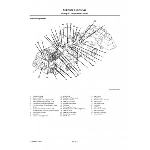
Main Component (Overview)
Main Component
Main Component
Electric Component Layout (Front Chassis)
Electric Component Layout (Rear Grill)
Electrical System (Cab)
Electrical System (Around Battery Box)
Electrical System (Around Hydraulic Tank)
Electrical System (Around Fuel Tank)
Electrical System (Rear Chassis Center Frame)
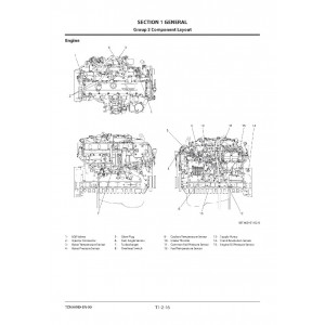
Engine
Aftertreatment Device
Hydraulic Pump
Transmission and Torque Converter Assembly
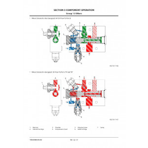
Multiple Control Valve
Unloader Valve (Brake Charge Valve) and Combination Valve (Brake Manifold Valve)
Steering Valve
Flow Regulator Valve
Ride Control Valve (Option)
Fuel Priming Pump (us Option)
Secondary Steering Pump (Option)
Component Specifications
Engine
Engine Accessories
Hydraulic Component
Electrical Component
1 Controller
Outline
CAN Circuit
Control System
Outline
Engine Control
Pump Control
Transmission Control
Fan Control, Valve Control
Other Controls
Combined Electric and Hydraulic ControlCircuit
Engine System
Outline
Engine Sensors
Fuel Injection Control
EGR Control
Preheating Control
Variable Turbocharger Control
Urea SCR System
Engine Output Restriction (Inducement)
Aftertreatment Device
Aftertreatment Device Regeneration Control
Hydraulic System
Outline
Pilot Circuit
Brake Priority Circuit
Service Brake Circuit
Parking Brake Circuit
Auto Brake Circuit
Lift Arm (Boom) / Bucket Operation ControlCircuit
Fan Circuit
Main Circuit
Steering Priority Circuit
Steering Operation Control Circuit
Neutral Circuit
Flow Rate Control Circuit
Relief Circuit
Other Circuits
Pump Control Circuit
Parallel Circuit Flow Rate Control
Single Operation Circuit
Combined Operation Circuit
Ride Control Circuit
Emergency (Secondary) Steering Circuit(Option)
Electrical System
Outline
Main Circuit
Electric Power Circuit (Key Switch: OFF)
CAN Circuit
Accessory Circuit (Key Switch: ACC)
Starting Circuit (Key Switch: START)
Neutral Engine Start Circuit
Charging Circuit (Key Switch: ON)
Surge Voltage Prevention Circuit
Pilot Shut-Off Circuit (Key Switch: ON)
Auto Shut-Down (Idling Stop) Circuit
Engine Stop Circuit
Monitor Circuit
Air Conditioner Circuit
Steering Column Monitor Circuit
Head Light Circuit
Hazard Light Circuit (Key Switch: OFF)
Turn Signal Light Circuit
Horn Circuit (Key Switch: OFF)
Reverse Light/Buzzer Circuit
Brake Light Circuit
Parking Brake Circuit
Accessory Circuit
Work Light Circuit
Wiper Circuit
Cab Light Circuit
COMPONENT OPERATION
Pump Device
Hydraulic Pump Outline
Main Hydraulic Pump
Regulator
Accessory Pump
Pump Delivery Pressure Sensor
Control Valve
Outline
Hydraulic Circuit
Main Relief Valve
Main Relief Valve Operation
Overload Relief Valve (with Make-UpFunction)
Bleed-Off Compensation Spool
Bucket Spool
Lift Arm (Boom) Spool
Lift Arm Flow Rate Control Valve
Ride Control (Option)
Pump Control Valve (Negative Control ReliefValve)
Cooling Fan System
Cooling Fan System Layout
Fan Pump (Accessory Pump)
Fan Motor
Fan Control Valve
Steering Pilot Valve
Steering Pilot Line
Unit Location
Steering Pilot Valve
Joystick Steering Control Valve
Steering Valve
Outline
Operation
Steering Valve Meter-In Compensator
Steering Main Relief Valve
Steering Overload Relief Valve
Steering Spool Variable Orifice
Steering Pilot Circuit and Its Operation
Flow Amplifier Notch and Pilot Orifice
Pilot Valve
Outline (Fingertip Control Type Pilot Valvefor Front Attachment)
Operation
Electromagnetic Detent
Outline (Joystick Type Pilot Valve for FrontAttachment)
Operation
Electromagnetic Detent
Charging Circuit
Outline
Brake Charge Valve
Combination Valve (Manifold Block)
Combination Valve (Solenoid Valve Block)
Service Brake Accumulator
Drive Unit
Outline
Transmission and Torque Converter Assembly
Drive Unit Hydraulic Circuit Diagram
Torque Converter (Lock-Up)
Transmission
Operation of Transmission
Clutch Pack
Power Flow Path in the Transmission
Transmission Control Valve
Lock-Up Clutch Valve Assy
Axle
Outline
Front Axle Assembly
Rear Axle Assembly
Differential Gear (Conventional Type)
Limited Slip Differential (LSD) (Option)
Service Brake
Parking Brake
Parking Brake Manual Release
Brake Valve
Outline
Service Brake Operation
Bleed Air from Service Brake Circuit
Pressure Switch (for Stop Lamp)
Pressure Sensor (for Declutch)
Auto Brake Operation
Bleed Air from Auto Brake Circuit
DEF Supply System
System Overview
DEF
DEF Tank
Hose Urea
DEF Sensor Unit
DEF Supply Module
Coolant Line
Coolant Control Valve Air Bleeding Procedure
Others
Propeller Shaft
Emergency (Secondary) Steering Pump(Option)
Flow Regulator Valve
Ride Control Valve (Option)
Ride Control Accumulator
Steering Accumulator
Priority Hammer Valve
Axle Oil Cooler
6. Operational Principle Manual (TONHK40-EN-00)
Format: PDF, 497 pages
Language: English
Table of Contents:
GENERAL
Specifications
Component Layout
Component Specifications
SYSTEM
Controller
Control System
Engine System
Hydraulic System
Electrical System
COMPONENT OPERATION
Pump Device
Control Valve
Cooling Fan System
Steering Pilot Valve
Steering Valve
Pilot Valve
Charging Circuit
Drive Unit
Axle
Brake Valve
DEF Supply System
Others
SERVICE MANUAL REVISION REQUEST FORM
7. Wiring Diagram (TTNHK70-EN-00_Circuit)
Format: PDF, 17 pages
Language: English
Table of Contents:
HYDRAULIC CIRCUIT DIAGRAM
FAN, PILOT AND BRAKE CIRCUIT DIAGRAM
ELECTRICAL CONNECTION DIAGRAM (1/4)
ELECTRICAL CONNECTION DIAGRAM (2/4)
ELECTRICAL CONNECTION DIAGRAM (3/4)
ELECTRICAL CONNECTION DIAGRAM (4/4)
FRONT CHASSIS CABLE LAYOUT AND WIRING DIAGRAM
REAR CHASSIS WIRING DIAGRAM (1/3)
REAR CHASSIS WIRING DIAGRAM (2/3)
REAR CHASSIS WIRING DIAGRAM (3/3)
FLOOR WIRING DIAGRAM (REAR CONSOLE) (1/3)
FLOOR WIRING DIAGRAM (REAR CONSOLE) (2/3)
FLOOR WIRING DIAGRAM (REAR CONSOLE) (3/3)
FLOOR WIRING DIAGRAM (SIDE CONSOLE)
JOYSTICK STEERING SYSTEM (USA)
FLOOR WIRING DIAGRAM (FRONT CONSOLE)
CAB WIRING DIAGRAM
8. Wiring Diagram (TTNHK40-EN-00_Circuit_2)
Format: PDF, 15 pages
Language: English
Table of Contents:
FLOOR CABLE LAYOUT (REAR AND SIDE CONSOLES)
FLOOR WIRING DIAGRAM (REAR CONSOLE) (1/3)
FLOOR WIRING DIAGRAM (REAR CONSOLE) (2/3)
FLOOR WIRING DIAGRAM (REAR CONSOLE) (3/3)
FLOOR WIRING DIAGRAM (SIDE CONSOLE)
FLOOR WIRING DIAGRAM (STEERING POST)
FLOOR CABLE LAYOUT (FRONT CONSOLE)
FLOOR WIRING DIAGRAM (FRONT CONSOLE)
CAB CABLE LAYOUT
CAB WIRING DIAGRAM
HYDRAULIC CIRCUIT DIAGRAM OF OPTIONAL SYSTEM
JOYSTICK STEERING ELECTRICAL CONNECTION DIAGRAM
JOYSTICK STEERING CABLE LAYOUT (REAR AND SIDE CONSOLE) (OPTION)
JOYSTICK STEERING WIRING DIAGRAM (REAR & SIDE CONSOLES)
JOYSTICK STEERING WIRING DIAGRAM (ARMREST HARNESS)
9. Wiring Diagram (TTNHK40-EN-00_Circuit_1)
Format: PDF, 14 pages
Language: English
Table of Contents:
HYDRAULIC CIRCUIT DIAGRAM
FAN, PILOT AND BRAKE CIRCUIT DIAGRAM
ELECTRICAL CONNECTION DIAGRAM (1/4)
ELECTRICAL CONNECTION DIAGRAM (2/4)
ELECTRICAL CONNECTION DIAGRAM (3/4)
ELECTRICAL CONNECTION DIAGRAM (4/4)
FRONT CHASSIS CABLE LAYOUT AND WIRING DIAGRAM
REAR CHASSIS CABLE LAYOUT(1/3)
REAR CHASSIS CABLE LAYOUT (2/3)
REAR CHASSIS CABLE LAYOUT (3/3)
REAR CHASSIS WIRING DIAGRAM (1/3)
REAR CHASSIS WIRING DIAGRAM (2/3)
REAR CHASSIS WIRING DIAGRAM (3/3)
FLOOR CABLE LAYOUT
| Included in the package | |
| Workshop Manual | 2 |
| Troubleshooting Manual | 2 |
| Operational Principle Manual | 2 |
| Wiring Diagram | 3 |
| Covered | |
| Model Class | ZW550 |
| Generation | 6 |
| Truck Type | Wheel Loader |
| Truck Models | ZW550-6 |
Hitachi Zaxis ZW550-6 Wheel Loader set of Service Manuals
- Brands Hitachi
- Product Code:Hitachi::ZW550-6
- Availability:Ready to instant download
-
$23.00
Tags: Zaxis ZW550-6.


.pdf-1-300x300.jpg)
.pdf-130-300x300.jpg)
.pdf-111-300x300.jpg)
.pdf-509-300x300.jpg)
.pdf-1-300x300.jpg)
.pdf-78-300x300.jpg)
.pdf-124-300x300.jpg)
.pdf-186-300x300.jpg)
