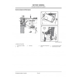
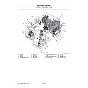
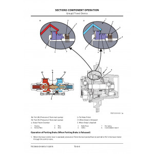
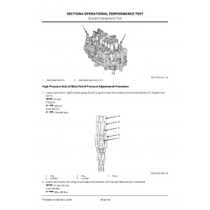
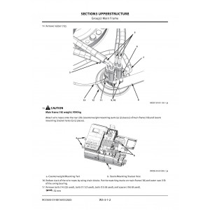
All-Inclusive Factory Service Technical manual for Hitachi Crawler Excavators Models Zaxis 300LC-7 and Zaxis 300LCN-7.
This manuals will assist you in diagnosing, repairing, troubleshooting, and operating for your crawler excavator.
You can use a Windows, Mac, or Android device to view this manuals. You only need to have a PDF reader installed.
Covered Models:
Zaxis 300LC-7
Zaxis 300LCN-7
The manual comprises 6 documents, including the Workshop Manual, Troubleshooting Manual, Operational Principle Manual, Operators Manual, and two Wiring Diagrams
1. Workshop Manual (WDD650-EN-00)
Format: PDF, 770 pages
Language: English
Table of Contents:
GENERAL
Precautions for Disassembling and Assembling
Tightening
Painting
Bleeding Air
Preparation
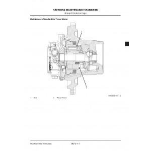
MAINTENANCE STANDARD
Upperstructure
Undercarriage
Front Attachment
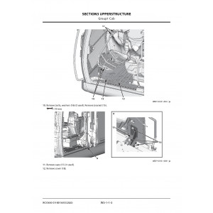
UPPERSTRUCTURE
Cab
Counterweight
Main Frame
Engine
Radiator Assembly
UPPERSTRUCTURE
Hydraulic Oil Tank
Fuel Tank
Pump Device
Control Valve
Swing Device
Pilot Valve
2. Troubleshooting Manual (TTDD650-EN-00)
Format: PDF, 706 pages
Language: English
Table of Contents:
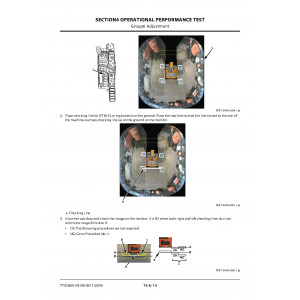
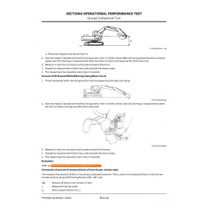
OPERATIONAL PERFORMANCE TEST
Introduction
Standard
Engine Test
Machine Performance Test
Component Test
Adjustment
TROUBLESHOOTING
Diagnosing Procedure
Monitor
e-Service
Component Layout
Troubleshooting A
Troubleshooting B
Air Conditioner
SERVICE MANUAL REVISION REQUEST FORM
The Attached Diagram List
3. Operational Principle Manual (TODD650-EN-00)
Format: PDF, 481 pages
Language: English
Table of Contents:
GENERAL
Specifications
Component Layout
Component Specifications
SYSTEM
Controller
Control System
Engine System
Hydraulic System
Electrical System
COMPONENT OPERATION
Pump Device
Swing Device
Control Valve
Pilot Valve
Travel Device
Signal Control Valve
Others (Upperstructure)
Others (Undercarriage)
4. Operators Manual (ENMDFY-EN1-1)
Format: PDF, 125 pages
Language: English
Table of Contents:
BEFORE OPERATION
Name of Components
Getting ON and OFF the Machine
About Aftertreatment Device
OPERATOR'S STATION
Layout of Equipment in Operator's Station (Illustration Contents)
Multi Function Monitor
Auto Air Conditioner
Audio Operation
Switch Panel (Illustration Content)
Switch Panel (for Optional Equipments)
Control Lever
Facilities in Operator's Station
Aerial Angle
Installation and Adjustment of Mirrors
Emergency Exit
Battery Disconnect Switch
BREAK-IN
Observe Engine Operation Closely
Every 8 Hours or Daily
After the First 50 Hours
After the First 100 Hours
OPERATING THE ENGINE
Inspect Machine Daily Before Starting
Before Starting the Engine
Starting the Engine
Check Instruments After Starting
Using the Booster Battery
Stopping the Engine
Engine Auto-Stop at Extremely Low Temperatures
DRIVING THE MACHINE
Travel Levers and Pedals
Travel Mode Switch
Traveling on Soft Ground
Raising One Track Using the Boom and Arm
Retrieval
Operating in Water or Mud
Parking the Machine on Slopes
Parking
Prohibition of Sudden Control Operations when Traveling at High Speed
Prohibition of Traveling for Long Periods
OPERATING THE MACHINE
Control Lever (ISO Pattern)
Pilot Shut-Off Lever
Warming-Up Operation
Engine Speed Control
Auto-Idle
Auto Shut-Down
Aftertreatment Device Manual Regeneration
Attachments
Power Boost Switch
Power Mode
Attachment Settings
Operating Backhoe
Shovel
Grading Operation
Do Not Strike the Ground with Bucket Teeth
Avoid Hammer Work
Avoid Abusive Operation
Never Move an Object Sideways with the Bucket
Retracting the Arm and Bucket
Never use Wide Track Shoes on Rough Ground
Shackle Hole Usage
Pilot Accumulator Functions
How to Lower Boom in Case of Emergency and When Engine Stops (Without hose-rupture safety valve)
How to Lower Front Equipment and Attachment in Case of Emergency and When Engine Stops (With hose-rupture safety valve)
Precautions for After Operations
TRANSPORTING
Transporting by Road
Loading/Unloading on a Trailer
Fastening the Machine for Transport
Unloading
Lifting the Machine
MAINTENANCE
Correct Maintenance and Inspection Procedures
Layout
Inspection and Maintenance Intervals
Preparation for Inspection and Maintenance
Hood and Access Covers
Maintenance Guide
Periodic Replacement of Parts
Kind of Oils
List of Consumable Parts
A. Greasing
Electric Grease Gun (Only ZX330-7 Class)
Using the Electric Grease Gun
B. Engine
C. Transmission
D. Hydraulic System
E. Fuel System
F. Air Cleaner
G. Cooling System
H. Electrical System
I. Miscellaneous
J. Aftertreatment Device
K. Urea SCR System
L. Aerial Angle
HYDRAULIC CIRCUIT
Hydraulic Circuit
MAINTENANCE UNDER SPECIAL ENVIRONMENTAL CONDITIONS
STORAGE
Storing the Machine
TROUBLESHOOTING
SPECIFICATIONS
Specifications ZX250LC-7, 250LCN-7
Working Ranges ZX250LC-7, 250LCN-7
Shoe Types and Applications ZX250LC-7
Shoe Types and Applications ZX250LCN-7
Bucket Types and Applications ZX250LC-7, 250LCN-7
Specifications ZX300LC-7, 300LCN-7
Working Ranges ZX300LC-7, 300LCN-7
Shoe Types and Applications ZX300LC-7
Shoe Types and Applications ZX300LCN-7
Bucket Types and Applications ZX300LC-7, 300LCN-7
Specifications ZX350LC-7, 350LCN-7
Working Ranges ZX350LC-7, 350LCN-7
Shoe Types and Applications ZX350LC-7
Shoe Types and Applications ZX350LCN-7
Bucket Types and Applications ZX350LC-7, 350LCN-7
The Value of the Carbon Dioxide (CO2) emissions
OPTIONAL ATTACHMENTS AND DEVICES
Link with Hook
Bucket Teeth (Transverse-Type-Pin-Used Type)
Replacement Procedure
2-Piece Boom
Attachment Pedal
Hydraulic Breaker, Crusher, Quick Hitch
INDEX
Blank Page
5. Wiring Diagram (TTDD650-EN-00_circuit)
Format: PDF, 17 pages
Language: English
Table of Contents:
ELECTRICAL CIRCUIT DIAGRAM
CONNECTORS
CAB HARNESS
MAN HARNESS
PUMP HARNESS
NOx HARNESS
MONITOR HARNESS
CONSOLE HARNESS
CONTROL VALVE HARNESS
WIPER HARNESS
WIPER MOTOR HARNESS
PILOT SHUT-OFF SOLENOID VALVE HARNESS
ENGINE STOP SWITCH HARNESS
CIGAR LIGHTER SUB HARNESS
HYDRAULIC CIRCUIT DIAGRAM (MONO BOOM)
HYDRAULIC CIRCUIT DIAGRAM (OPTION) (2-PIECE BOOM, AFL 1ch)
HYDRAULIC CIRCUIT DIAGRAM (OPTION) (2-PIECE BOOM, AFL 2ch)
6. Wiring Diagram (TTDD650-EN-00CIR)
Format: PDF, 13 pages
Language: English
Table of Contents:
ELECTRICAL CIRCUIT DIAGRAM (OPTION)
CONSOLE HARNESS (OPTION)
CAB REAR HARNESS
REAR HEADLIGHT HARNESS
REAR HEADLIGHT SWITCH HARNESS
REAR HEADLIGHT SUB HARNESS
HEADLIGHT HARNESS
AFL HARNESS (REAR SIDE) (1ch and 2ch)
AFL MAIN HARNESS (1ch)
AFL MAIN HARNESS (2ch)
CAMERA LIGHT HARNESS
BOOM LIGHT (RIGHT) HARNESS
AUXILIARY FLOW COMBINER HARNESS
| Included in the package | |
| Workshop Manual | 1 |
| Troubleshooting Manual | 1 |
| Operational Principle Manual | 1 |
| Operators Manual | 1 |
| Wiring Diagram | 2 |
| Covered | |
| Model Class | ZAXIS 300 |
| Generation | 7 |
| Truck Type | Crawler Excavator |
| Truck Models | ZAXIS 300LC-7, ZAXIS 300LCN-7 |
Hitachi Zaxis 300LC-7 and Zaxis 300LCN-7 Crawler Excavator set of Service Manuals
- Brands Hitachi
- Product Code:Hitachi::ZX300LC-7
- Availability:Ready to instant download
-
$23.00
Tags: Zaxis 300LC-7, Zaxis 300LCN-7

