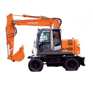
All-Inclusive Factory Service Technical manual for Hitachi Wheel Excavators Models Zaxis 145W-3.
This manuals will assist you in diagnosing, repairing, troubleshooting, performing perfomance checks, repairing engine, maintaining, operating, and other for your wheel excavator.
You can use a Windows, Mac, or Android device to view this manuals. You only need to have a PDF reader installed.
Covered Models:
Zaxis 145W-3
The manual comprises 12 documents, including the Workshop Manual, Troubleshooting Manual, Perfomance Check and Troubleshooting Manual, Engine Technical Manual, Maintenance Manual, two Operational Principle Manuals, two Operators Manuals, two Wiring Diagrams, and Aditional Service Information
1. Workshop Manual (WCFA-E-00(20120323))
Format: PDF, 730 pages
Language: English
Table of Contents:
GENERAL
Precautions for Disassembling and Assembling
Tightening
Painting
Bleeding Air from Hydraulic Oil Tank
UPPERSTRUCTURE
Cab
Counterweight
Main Frame
Pump Device
Control Valve
Swing Device
Pilot Valve
Electric Lever
Signal Control Valve
Shockless Valve
Solenoid Valve
Pilot Shut-Off Solenoid Valve
Steering Valve
Brake Valve
Accumulator Charge Valve
UNDERCARRIAGE
Swing Bearing
Travel Motor
Center Joint
Transmission
Axle
Axle Lock Cylinder
Operate Check Valve
Suspension Cylinder
Pilot Check Valve
Solenoid Valve
Transmission Changeover Solenoid Valve
Propeller Shaft
ATTACHMENT
Front Attachment
Cylinder
Hose Rupture Valve
Operate Check Valve
2. Troubleshooting Manual (TTCFA-E-00(20150213))
Format: PDF, 624 pages
Language: English
Table of Contents:
OPERATIONALPERFORMANCE TEST
Introduction
Engine Test
Excavator Test
Component Test
TROUBLESHOOTING
Diagnosing Procedure
Monitor Unit
Dr. ZX
ICF
Troubleshooting A
Troubleshooting B
Electrical System Inspection
3. Perfomance Check and Troubleshooting Manual (TTLA0722)
Format: PDF, 583 pages
Language: English
Table of Contents:
OPERATIONAL PERFORMANCE TEST
Introduction
Standard
Engine Test
Excavator Test
Componebt Test
SCTION 5 TROUBLESHOOTING
Diagnosing Procedure
Monitor Unit
Dr. ZX
ICF
Component Layout
Troubleshooting A
Troubleshooting B
Electrical System Inspection
4. 4JJ1 Engine Technical Manual (KM-4JJ1-E-01)
Format: PDF, 804 pages
Language: English
Table of Contents:
4JJ1 Electronic Control Fuel Injection System (Common Rail Type)
How to Use This Manual
Precautions on Service Work
Procedure of Trouble Diagnosis
How to Inspect Injector
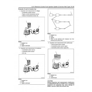
How to Use Breaker Box
Engine Control System
List of Function Checks
List of Diagnostic Trouble Codes
List of Trouble Symptom
Special Tool
4JJ1 Engine Mechanical
ISUZU Diesel Engine
Engine Foot
Cylinder Head Cover
Intake Manifold
Exhaust Manifold
Timing Gear Train
Camshaft
Rocker Arm
Valve Stem Seal, Valve Spring
Cylinder Head
Piston, Connecting Rod
Flywheel
Gear Case ASM
Crankshaft Front Oil Seal
Crankshaft Rear Oil Seal
Crankshaft
Cylinder Block
Special Tool
4JJ1 Cooling System
Cooling System
Water Pump
Thermostat
Drive Belt
Fan Clutch, Cooling Fan
4JJ1 Fuel System
Fuel System
Fuel Filter ASM
Fuel Filter Element
Fuel Injector
Common Rail
Fuel Supply Pump
Strainer
Suction Control Valve
Electromagnetic Pump Filter
Special Tool
4JJ1 Electrical System
Electrical System
Charging System
Generator (24V model)
Generator (12V model)
Starting System
Starter (24V model)
Starter (12V model)
4JJ1 Exhaust System
EGR System
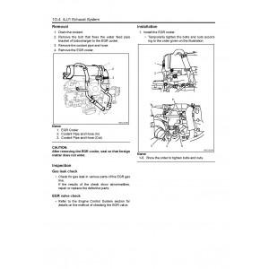
EGR Cooler
Exhaust System
Turbocharger
Turbocharger Inlet Duct
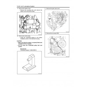
4JJ1 Lubrication System
Lubrication System
Oil Filter
Oil Port Cover ASM
Oil Cooler
Oil Relief Valve
Crankcase, Oil Pan
Oil Pump
Oil Pressure Switch
Special Tool
4JJ1 Preheating System
Preheating System
5. Maintenance Manual (TTLA0735)
Format: PDF, 213 pages
Language: English
Table of Contents:
MAINTENANCE
Correct Maintenance and Inspection Procedures
Check the Hour Meter Regularly
Use Correct Fuels and Lubricants
Layout
Maintenance Guide Table
Prepare Machine for Maintenance
Hood and Access Covers
Periodic Replacement of Parts
Maintenance Guide
HYDRAULIC CIRCUIT AND ELECTRICAL CIRCUIT
Hydraulic Circuit
Electrical Circuit
Electrical Diagram
MAINTENANCE UNDER SPECIAL ENVIRONMENTAL CONDITIONS
Maintenance Under Special Environmental Conditions
STORAGE
Storing the Machine
Removing the Machine from Storage
TROUBLESHOOTING
Troubleshooting
SPECIFICATIONS
Specifications (ZAXIS140W-3) (Standard CHASSIS, REAR BLADE)
Specifications (ZAXIS140W-3) (Standard CHASSIS, REAR OUTRIGGER)
Specifications (ZAXIS140W-3) (FRONT BLADE REAR OUTRIGGER)
Specifications (ZAXIS140W-3) (FRONT OUTRIGGER REAR BLADE)
Specifications (ZAXIS140W-3) (FRONT OUTRIGGER REAR OUTRIGGER)
Working Ranges ZAXIS140W-3 MONOBLOCK BOOM
Working Ranges ZAXIS140W-3 2-PIECE BOOM
Specifications (ZAXIS170W-3) (Standard GAUGE, Standard CHASSIS, REAR BLADE)
Specifications (ZAXIS170W-3) (Standard GAUGE, Standard CHASSIS, REAR OUTRIGGER)
Specifications (ZAXIS170W-3 (Standard GAUGE, FRONT BLADE REAR OUTRIGGER)
Specifications (ZAXIS170W-3) (Standard GAUGE, FRONT OUTRIGGER REAR BLADE)
Specifications (ZAXIS170W-3) (Standard GAUGE, FRONT OUTRIGGER REAR OUTRIGGER)
Working Ranges ZAXIS170W-3 MONOBLOCK BOOM
Working Ranges ZAXIS170W-3 2-PIECE BOOM
Specifications (ZAXIS190W-3 )(Standard CHASSIS, REAR BLADE)
Specifications (ZAXIS190W-3) (Standard CHASSIS, REAR OUTRIGGER)
Specifications (ZAXIS190W-3) (FRONT BLADE REAR OUTRIGGER)
Specifications (ZAXIS190W-3) (FRONT OUTRIGGER REAR BLADE)
Specifications (ZAXIS190W-3) (FRONT OUTRIGGER REAR OUTRIGGER)
Working Ranges ZAXIS190W-3 MONOBLOCK BOOM
Working Ranges ZAXIS190W-3 2-PIECE BOOM
Specifications (ZAXIS210W-3) (Standard GAUGE, REAR BLADE)
Specifications (ZAXIS210W-3) (Standard GAUGE, REAR OUTRIGGER)
Specifications (ZAXIS210W-3) (Standard GAUGE, FRONT BLADE REAR OUTRIGGER)
Specifications (ZAXIS210W-3) (Standard GAUGE, FRONT OUTRIGGER REAR BLADE)
Specifications (ZAXIS210W-3) (Standard GAUGE, FRONT OUTRIGGER REAR OUTRIGGER)
Working Ranges ZAXIS210W-3 MONOBLOCK BOOM
Working Ranges ZAXIS210W-3 2-PIECE BOOM
Sound Level Results (2000/14/EC)
OPTIONAL ATTACHMENTS AND DEVICES
Blade and Outrigger
Maintenance
2-Piece Boom
Maintenance (2-piece Boom)
Lifting Capacities (ZAXIS140W-3)
Lifting Capacities (ZAXIS170W-3)
Lifting Capacities (ZAXIS190W-3)
Lifting Capacities (ZAXIS210W-3)
6. Operational Principle Manual (TTLA0721)
Format: PDF, 517 pages
Language: English
Table of Contents:
GENERAL
Specifications
Component Layout
Component Specifications
SYSTEM
Controller
Control System
ECM System
Hydraulic System
Electrical System
COMPONENT OPERATION
Pump Device
Swing Device
Control Valve
Pilot Valve
Electric Lever
Transmission
Axle
Travel Motor
Signal Control Valve
Steering Valve
Brake Valve
Others (Upperstructure)
Others (Undercarriage)
7. Operational Principle Manual (TOCFA-E-00(20120323))
Format: PDF, 530 pages
Language: English
Table of Contents:
Specifications
Specifications
Working Ranges
Component Specifications
Engine
Engine Accessories
Hydraulic Component
Electrical Component
Component Layout
Main Component Layout
Electrical System (Overview)
Electrical System (Monitors and Switches)
Electrical System (Controllers and Relays)
Engine
Pump Device
Swing Device
Signal Control Valve
Control Valve
Brake Valve
Spool Solenoid Valve Unit
Solenoid Valve Unit (For Electric Lover)
Travel Shockless Valve
TransmissionChangeover Solenoid Valve
Travel Device
Filter
SYSTEM
Controller
Control System
ECM System
Hydraulic System
Electrical System
COMPONENT OPERATION
Pump Device
Swing Device
Control Valve
Pilot Valve
Electric Lever
Transmission
Axle
Travel Motor
Signal Control Valve
Outline
Pilot Port
Shuttle Valve
Shockless Valve
Pump 1 and Pump 2 Flow Rate Control Valves
Bucket Flow Rate Control Valve Control Spool, Swing Parking Brake Release Spool
Steering Valve
Outline
Steering Valve
Operation
Overload Relief Valve
Make-Up Valve
Priority Valve
Operation
Relief Valve
Brake Valve
Outline
Operation
Others (Upperstructure)
Pilot Shut-Off Solenoid Valve
Transmission Changeover Solenoid Valve
Solenoid Valve
Travel Shockless Valve
Accumulator Charging Valve
Hose Rupture Valve
Accumulator
Pilot Relief Valve
Machine Height Control Valve(Optional)
Others (Undercarriage)
Swing Bearing
Center Joint
Slip Ring
Cylinder
Suspension Cylinder (Optional)
Accumulator (Optional)
8. Operators Manual (TTLA0734)
Format: PDF, 161 pages
Language: English
Table of Contents:
OPERATION
COMPONENTS NAME
Cab Features (Standard Model)
Steering Column Console
Steering Wheel and Travel Horn Switch
Accelerator Pedal
Brake Pedal
Forward/Reverse Travel Switch
Combination Switch(Turn Signal Switch, Light and Dimmer Switches)
Brake Switch
Hazard Switch
Operator’s Station
Key Switch
Right/Left Control Levers
Lever Switch
Lighter
Cab Light
Installing Fire Extinguisher (Optional)
Pilot Control Shut-off Lever
Engine Stop Switch
Multi Function Monitor
Basic Screen
Monitor Operation
Displaying Basic Screen
Trip Meter (7)
Odometer (8)
Hour Meter (9)
Clock (18)
Fuel Gauge (25)
Coolant Temperature Gauge (30)
Brake Oil Pressure Gauge (33)
Travel Speed Meter (34)
Tachometer (35)
Back Monitor Screen Selector (22)
Menu Key (23)
Optional Function Keys (24, 27, 29 and 31)
Return-basic Screen Key (32)
Menu Screen
Displaying Basic Screen by Inputting Password (Optional)
Corrective Measures to be Taken when a Wrong Password is input
Extending Password Validity Time
Alarm Occurrence Screen
Clock Setting
Work Mode (Attachment Selection)
Attachment Adjustment (Pump 2 Flow Rate Adjustment)
Operating Status
Maintenance Setting
Mail (Optional)
Meter Display Control
Password Revising (Optional)
Back Monitor Setting
Language Setting
Meter Combination Setting
Unit Setting
Fuse Box
Additional Fuse Box
Auto Air Conditioner Operation
Tips for Optimal Air Conditioner Usage
Heater (Optional) Operation
Am/Fm Radio Operation
Digital Clock Setting Procedure
Cab Door Release Lever
Opening Upper Front Window
Closing Upper Front Window
Removing and Storing Lower Front Window
Opening Door Windows
Opening/Closing Overhead Window (Std. Model)
Opening/Closing Polycarbonate Type Roof Overhead Window (Clear Hatch: If Equipped)
Emergency Exit
Adjusting the Air-suspension Seat (Optional)
Seat with a Built-in Heater
Adjusting the Air-suspension Seat(Optional)
Seat with a Built-in Heater
Seat Belt
BREAK-IN
Observe Engine Operation Closely
Every 8 Hours or Daily
After the First 50 Hours
After the First 100 Hours
OPERATING THE ENGINE
Inspect Machine Daily Before Starting
Before Starting Engine
Starting the Engine in Ordinary Temperature
Starting in Cold Weather
Check Instruments After Starting
Using Booster Batteries
Stopping the Engine
DRIVING THE MACHINE
Traveling
Engine Speed Control
Travel Mode Switch
Stopping and Restarting
Instructions for Traveling on a Slope
Parking
Emergency Parking Due to Machine Failure
Travel Alarm (Optional)
OPERATING THE MACHINE
Control Lever (ISO Pattern) (Standard)
Control Lever (Hitachi Pattern)
Pilot Control Shut-off Lever
Steering Wheel Column
Warming-up Operation
Engine Speed Control
Auto-idle
Work Mode
Power Digging (Only ZAXIS210W-3)
Power Mode
Parking/Stopping the Machine on a Slope (In Case of Emergency)
Raising the Machine Front Above the Ground with the Boom and Arm Function
Excavation
Face Shovel Operation
Grading Operation
Do Not Slam the Bucket Teeth into the Ground
Do Not Use the Bucket as a Hammer
Avoid Increasing Digging Force Forcibly
Avoid Using Swing Power
Boom Lowering Procedure in Emergency or when the Engine Stalls
Overnight Storage Instructions
TRANSPORTING
Transporting by Road
Loading/Unloading on a Trailer
Transporting
Unloading
Towing Machine
9. Operators Manual (EMCGB-EN2-1)
Format: PDF, 494 pages
Language: English
10. Wiring Diagram (ZX145W-3_circuit_attach(20140414))
Format: PDF, 25 pages
Language: English
Table of Contents:
ELECTRICAL CIRCUIT DIAGRAM (STANDARD)(ZX145W-3: Up to serial No.010338/ ZX145W-3-AMS :Up to serial No.020117)
ELECTRICAL CIRCUIT DIAGRAM (STANDARD)(ZX145W-3: Serial No.010339 and up/ ZX145W-3-AMS: Serial No.020118 and up)
ELECTRICAL CIRCUIT DIAGRAM (OPTIONAL)(ZX145W-3: Up to serial No.010338/ ZX145W-3-AMS :Up to serial No.020117)
ELECTRICAL CIRCUIT DIAGRAM (OPTIONAL)(ZX145W-3: Serial No.010339 and up/ ZX145W-3-AMS: Serial No.020118 and up)
CONNECTORS
CAB HARNESS(ZX145W-3: Up to serial No.010338/ ZX145W-3-AMS :Up to serial No.020117)
CAB HARNESS (PRODUCTION APRIL 2010 AND UP)(ZX145W-3: Up to serial No.010338/ ZX145W-3-AMS :Up to serial No.020117)
CAB HARNESS(ZX145W-3: Serial No.010339 and up/ ZX145W-3-AMS: Serial No.020118 and up)
ENGINE HARNESS
FLOOR HARNESS
MONITOR HARNESS
CHASSIS HARNESS
LEFT CONSOLE HARNESS(ZX145W-3: Up to serial No.010338/ ZX145W-3-AMS :Up to serial No.020117)
LEFT CONSOLE HARNESS(ZX145W-3: Serial No.010339 and up/ ZX145W-3-AMS: Serial No.020118 and up)
AUXILIARY / POSITIONING SELECT HARNESS
BLADE / OUTRIGGER HARNESS
LICENSE PLATE HARNESS
POSITIONING HARNESS
PRESSURE SENSOR (POSITIONING) HARNESS
SWING PARKING BRAKE RELEASE HARNESS
ENGINE SUB HARNESS (1)
ENGINE SUB HARNESS (2)
BACK LAMP RELAYHARNESS(ZX145W-3: Up to serial No.010338/ ZX145W-3-AMS :Up to serial No.020117)
BACK LAMPRELAY HARNESS(ZX145W-3: Serial No.010339 and up/ ZX145W-3-AMS: Serial No.020118 and up)
HYDRAULIC CIRCUIT DIAGRAM (2-PIECE BOOM, FULLY OPTIONAL)
11. Wiring Diagram (ZX145W-3_circuit)
Format: PDF, 14 pages
Language: English
Table of Contents:
ZX145W-3 SELECTOR VALVE / SECONDARY PILOT RELIEFSELECTOR HARNESS (OPTIONAL)
ZX145W-3 FLOW RATE ADJUSTMENT ASSIST HARNESS (OPTIONAL)
ZX145W-3 ASSIST HARNESS (1) (OPTIONAL)
ZX145W-3 ASSIST HARNESS (2) (OPTIONAL)
ZX145W-3 ASSIST HARNESS (OPTIONAL)
ZX145W-3 BOOM BOTTOM PRESSURE SENSOR HARNESS (OPTIONAL)
Z145W-3 GRIP EXTENSION HARNESS (OPTIONAL)
ZX145W-3 GRIP EXTENSION HARNESS (FNR)
ZX145W-3 HEATER SEAT HARNESS (OPTIONAL)
ZX145W-3 OVERLOAD ALARM HARNESS (OPTIONAL)
ZX145W-3 OVERLOAD ALARM SUB HARNESS (OPTIONAL)
ZX145W-3 FLOW RATE SELECTOR HARNESS (OPTIONAL)
ZX145W-3 FRONT ATTACHMENT HARNESS (OPTIONAL)
ZX145W-3 MACHINE HEIGHT CONTROL SUB HARNESS (OPTIONAL)
12. Aditional Service Information (ZX145W-3_add)
Language: English
| Included in the package | |
| Workshop Manual | 1 |
| Troubleshooting Manual | 1 |
| Perfomance Check and Troubleshooting Manual | 1 |
| Engine Technical Manual | 1 |
| Maintenance Manual | 1 |
| Operational Principle Manual | 2 |
| Operators Manual | 2 |
| Wiring Diagram | 2 |
| Aditional Service Information | 1 |
| Covered | |
| Model Class | ZAXIS 145 |
| Generation | 3 |
| Truck Type | Wheel Excavator |
| Truck Models | ZAXIS 145W-3 |
Hitachi Zaxis 145W-3 Wheel Excavator set of Service Manuals
- Brands Hitachi
- Product Code:Hitachi::ZX145W-3
- Availability:Ready to instant download
-
$23.00
Tags: Zaxis 145W-3

.pdf-1-300x300.jpg)
.pdf-42-300x300.jpg)
.pdf-49-300x300.jpg)
.pdf-503-300x300.jpg)
.pdf-1-300x300.jpg)
.pdf-96-300x300.jpg)
.pdf-123-300x300.jpg)
.pdf-598-300x300.jpg)
.pdf-1-300x300.jpg)
.pdf-75-300x300.jpg)
.pdf-124-300x300.jpg)
.pdf-184-300x300.jpg)
